At AAOS 2021, Enhatch hosted an Innovation Theater discussion where CEO Peter Verrillo showed us how enabling technologies can limit rotation when practicing this widely-used technique.
Whiteside’s Line has been known to be a reliable reference in total knee arthroplasty surgical techniques since the mid-80’s. However, while it’s a very useful technique, it’s not perfect and won’t be 100% correct in every surgery. The problem: patient anatomy is different in each case and this technique can lead to femoral component malrotation.
An improved technique, Whiteside’s Line 2.0, can be used to help surgeons perform more accurate surgeries with better patient outcomes by leveraging Enhatch’s technology to design and develop patient matched instruments.
Enhancement of Surgical Principals
Unique patient anatomy and femoral component malrotation complicate conducting successful and accurate surgeries. Femoral component malrotation is a cause of pain, stiffness, patellofemoral complications and component failure in total knee arthroplasty (TKA).
What is Whiteside’s Line?
Traditionally, the AP axis (Whiteside’s Line) is represented by finding the center of the intercondylar notch posteriorly and the deepest point of the trochlear groove anteriorly, and then connecting the two points to create an axis (represented as a singular line). However, relying solely on this technique leads to parallax error as visualization of the 2D line changes depending on the surgeon’s viewpoint of the femur.
Current recommendations suggest that the combination of two or more anatomical landmarks such as the epicondylar axis and AP axis can be used to ensure proper alignment. Unfortunately, both epicondyles are relatively broad structures covered in dense soft tissue in vivo, making them difficult to identify intraoperatively.
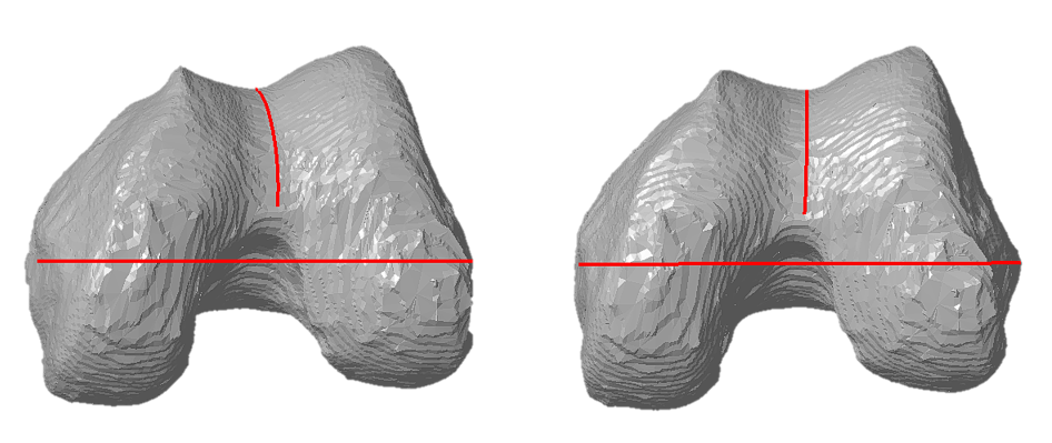
In order to improve accuracy and to avoid malrotation for the femoral implant, a 3D representation of the trochlear groove as the AP plane should be used. When the 3D representation of the AP plane becomes a line, the correct coronal alignment of the trochlear groove is achieved. In any other coronal orientation, the trochlear line looks like a curve.
Pre-operative Planning and Patient Matched Instrumentation with Enhatch
Enhatch’s Intelligent Surgery software segments radiographic images (X-Ray or CT scans) to create 3D models of patient bony anatomy. Using these models, Enhatch’s software can make measurements of anatomical landmarks pre-operatively.
The combination of 3D models of patient bony anatomy and measurements of anatomical landmarks allow for Enhatch’s Intelligent Surgery software to design and develop patient matched instrumentation. Patient matched instrumentation can greatly improve surgical outcomes by precisely placing implant components driven by the unique anatomy of the patient.